
Creating Scenery for the neXt Simulator
I’ve spent the past few weeks learning how to build scenery for the neXt simulator. If you haven’t tried neXt I highly recommend giving it a shot. It is, without a doubt, the most realistic RC heli simulator I’ve ever used (and I’ve used all of the top applications). It is so good that I decided it was worth my time to try to recreate our local flying field in the simulator. The developer provided some basic documentation for the process, but there were a lot of gaps to fill (due to my inexperience with Blender, mostly). I had never taken proper panoramic photos. I didn’t even know what a panoramic tripod head was. Cut to today… I built my own panoramic head (I’ll blog about this soon), I’ve gotten good at creating panoramic photos, and I can work my way around blender pretty well (at least for the purposes of creating a proper 3D scene).
Many thanks to Klaus Eiperle for being so helpful along the way…
Here’s the official documentation from neXt:
http://www.rc-aerobatics.eu/next-scenery-construction_e.html
Here’s what my process looks like. Your mileage may vary, but it should be helpful:
Step 1: Take Images
- Use a panoramic head on a level tripod.
- Overlap shots by 20-40%
- Start with lens parallel to ground. Aim for horizontal center to be on horizon (where ground meets sky in the distance all around you).
- Take 360 degrees of shots, tilt up so ground still slightly in view but mostly sky in view, go 360 again, point downward but with some of original first 360 subjects still in view, go 360, do one shot straight up, and one shot straight down.
Step 2: Process Images
- Open Raw files in Lightroom.
- Set first photo white balance as desired. Change dropdown to “Custom”.
- Select all photos and sync.
- Remove chromatic aberration on first photo. Select all photos and sync.
- Adjust exposure and use shadows, highlights, etc. to try to get all exposures on a level playing field. (Settings » Match Total Exposures might work too)
- enblend will be used later to automatically correct the differences in the exposures. It does a brilliant job at this.
- Export Raw files as JPEG 93% quality
- Regarding quality of JPEG: http://havecamerawilltravel.com/photographer/exporting-jpegs-lightroom-quality-settings
- ppi doesn’t matter afaik. Just use 72. http://theturninggate.net/2012/02/pixel-density-in-with-truth/
- Sharpen for Screen standard
Step 3: Build Panoramic Image
- Lookup the distortion values for the lens you used. It’s important to provide this to Hugin for better processing.
- Add files to Hugin via Photos tab.
- If you have a lens ini file available, use it.
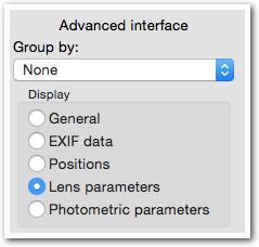
- After using lens profile, verify Lens parameters are correct, then go back to General mode. You do this with the Advanced Interface pane on the right side of the application. You must enable Advanced interface for this to appear.
- After using lens profile, verify Lens parameters are correct, then go back to General mode. You do this with the Advanced Interface pane on the right side of the application. You must enable Advanced interface for this to appear.
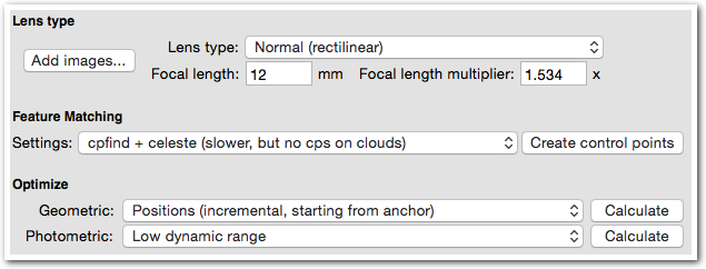
- If you do not have a lens file, set Focal length and multiplier accordingly by…
- Switch to Lens parameters mode (using Advanced Interface pane)
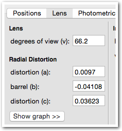
- Select all images, right click, choose Edit image variables
- Set values accordingly. Shown below are the settings I use for my Rokinon 12mm f/2.0
- Switch back to General mode
- Set Feature Matching to cpfind + celeste
- Click Create control points and wait patiently
- Click Calculate on Geometric optimization (this does the alignment)
- Open the Fast Panorama preview (icon with GL in top left corner)
- Carefully inspect image.
- If anything seems like it didn’t match up correctly you should…
- Go back to the Photos tab and change Geometric to Everything (or whatever other option you want).
- Run “Calculate” again.
- Open the Fast Panorama preview again and re-inspect the results; if ok now, move on.
- If anything seems like it didn’t match up correctly you should…
- If the panorama shots positioned well, proceed.
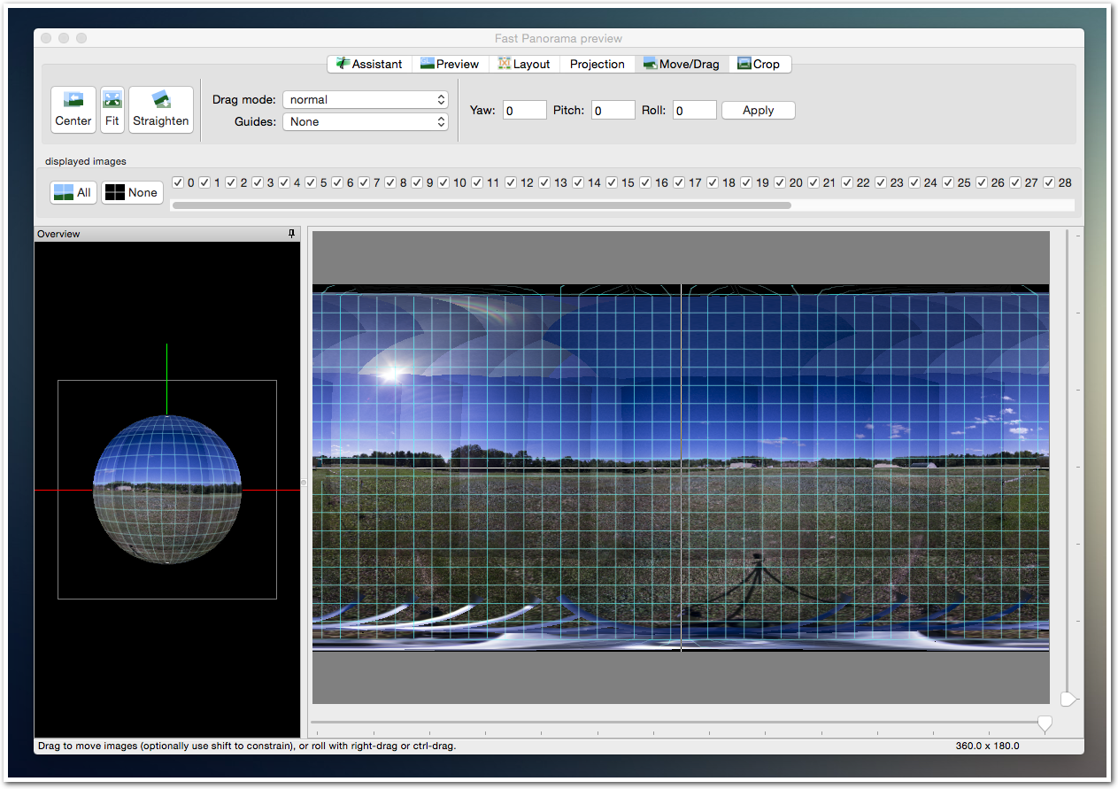
- Go into Move/Drag tab
-
Click and drag image at various points until horizon lined up and level across the photo.
- There are centered horizontal and vertical line.
- Use these to position the center of the photo and the horizon.
- You should drag different parts of the image to try to get as much of the ground-meets-sky line touching the horizontal center line as possible.
- Close fast preview window
- Go to Stitcher tab of main window
- Click Calculate optimal size
- Use TIFF for output
- When finished check file to make sure horizon is level. If yes, proceed…
Step 4: Convert Panoramic to 6-faces, separate files
- Open PTGui (trial version is fine)
- Tools » Convert to QTVR / cubic
- Add tiff file (the panoramic photo)
- Convert to “Cube faces, 6 separate files”
- Cube face size: 4096
- Click Convert
Step 5: Edit 6 faces tiff files
-
Fill in the gap at the top.
-
Clean up the tripod out of the bottom
-
Etc… but avoid changing anything near the edges, because the blending won’t look right between the images if you do.
Step 6: Prepare new neXt scenery directory
- Download template from http://www.rc-aerobatics.eu/next-scenery-construction_e.html
- Extract
- Rename to whatever you’re calling your scenery (SMRCHA in my case)
Step 7: Implement your image files
- Rename your 6 image files to “Mauchenmuehle.X.tif”
- Overwrite the image files in your scenery’s Textures directory
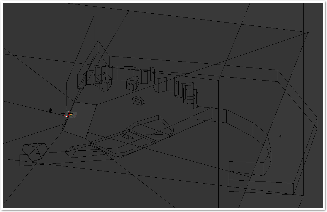
Step 8: Build your scenery
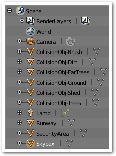
See all of the tips below. Here’s what my final scene hierarchy looks like:

Step 9: Submit scenery to the neXt developer
Before you can try your scenery in neXt it has to be built. The neXt developer will convert your blender project into a .next scenery file.
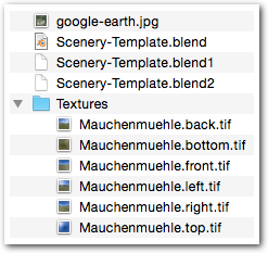
- Create a zip file of your project. It should look something like this:
- Send an email briefly explaining your scenery with questions, comments, etc. Contact information is at http://www.rc-aerobatics.eu/impressum_e.html
- Wait patiently for a response.
Step 10: Install your scenery
Follow the How to import sceneries instructions here: http://www.rc-aerobatics.eu/next-scenery_e.html
Google Earth overlay
- Go to google maps or Earth
- Zoom in to the area you’re going to be mapping
- Use the measuring tools to draw a square of known dimensions (e.g., 550 meters)
- Take screenshot of your square; save as “google-earth.jpg”
- Move screenshot into template neXt scenery folder
- Open the blender file and edit the “top” background image size (points to google-earth already). Set it to your square’s size, so 550m in this example
Now, when you go to top view (hit 7)you will see the Google Map overlay. Using this you can more easily create objects in the right places.
Drawing over the Google Maps overlay
I have minimal experience with Blender, but this works great for me:
- Go to Top view (with google map overlay)
- Set cursor to 0,0,0
- Click cursor somewhere near the object (preferably on a corner of the object)
- Add » Mesh » Plane
- S (to scale), then drag up until you have something you can easily manipulate
- Zoom in and delete 3 of the points (unless you want to start with a square).
- Ctrl-click along the outside edge of the object and go all the way around the object (use as few points as possible, going around corners and curves requires more points, of course)
- Shift-Right-Click on the last point you made, and the first point so that they are joined.
- Click “Extrude” tool.
- Transform and drag the “z” value up so that your shape becomes 3 dimensional.
Tips for working with neXt scenery in Blender
… from a Blender novice, so take these with a grain of salt…
- Pan with Shift – Option – Left click and drag
- Rotate with Option – Left click and drag
- Your camera should always be at 0, 0, 0.
- Before placing a new object, put 3d cursor where you want the object. (easiest to use google map overlay (top mode) to click for x,y. Then just update “Z” to 0.
- Most of your objects should have their lowest points at the ground level (z = -1.75m)
- Ground and runway should be at -1.75m if your area is flat. If your land is not flat, you can adjust as needed.
- “b” is your friend — use it to select vertices, edges, and faces easily.
- To move a point to a specific “z” first ensure your pivot point is the 3d cursor. Next, set your 3D Cursor position to have a Z of 0. Lastly, select the item you want to move (usually a point/vertex) and type S Z 0 (then enter). Don’t forget to set your pivot point back to Active Element
- Magic Mouse user? If scrolling your mouse leads to rotation you should fix this. View this video: https://www.youtube.com/watch?v=T-JHogscHJ8
- If you don’t have three mouse buttons I suggest emulating three-button mouse (it’s in the Input preferences)
- If you don’t have a number pad I suggest emulating the numpad (it’s in the Input preferences)
- Don’t judge positioning of objects from ANY VIEW except Top and Camera. You can get everything close with whatever views you want, but ultimately the Camera perspective is the one that matters, because that’s what you’ll see when you’re simming in neXt. So, when it comes time to check your work (let’s say you created a new cube that will represent a picnic table), first switch to camera view (hit 0), then hit SHIFT-f and move your mouse to look around. If it looks right from this perspective, it should look right in the simulator.
- Use TAB to switch between edit and object modes
- Rotation of objects is easiest if you have pivot point set to Active Element, using top view hit “r” and then move your mouse to rotate
- While in edit mode, hit “a” to select everything.
- If you have things selected, hit “a” to unselect them.
- Split an edge (add a vertex) easily by clicking the knife tool in the tools bar. Click the first edge, then click a second edge, then hit enter. If you need an even split you can do something like switch to edge mode, right click the edge to split, hit Ctrl-R, move mouse to see options and click to create new edges.
- Moving objects on x,y is easiest by going to top view (hit 7). Make sure you’re using 3d manipulator (the colorful lines). Select the object or vertices, or edges, or whatever. Then just drag the arrows to move the selection.
- Runway is where the heli can land. CollisionObj-Ground is where the heli will crash if it hits the ground.
One Comment
Harald Bendschneider
Hello Adam,
your description of the next scenery is already more detailed than the one from the manufacturer’s site. Thank you very much! I will try to construct my scenery “Scythe Mill” after it. In the template scenery I see in the skybox the faces of the cube faces, but the photos are missing. How do you put the objects in the right place then?
Best regards
Harald
http://www.pano4all.de